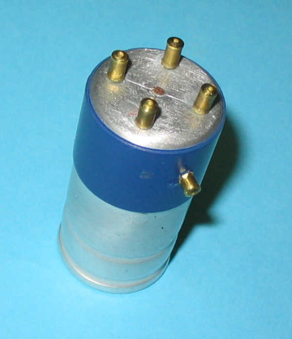
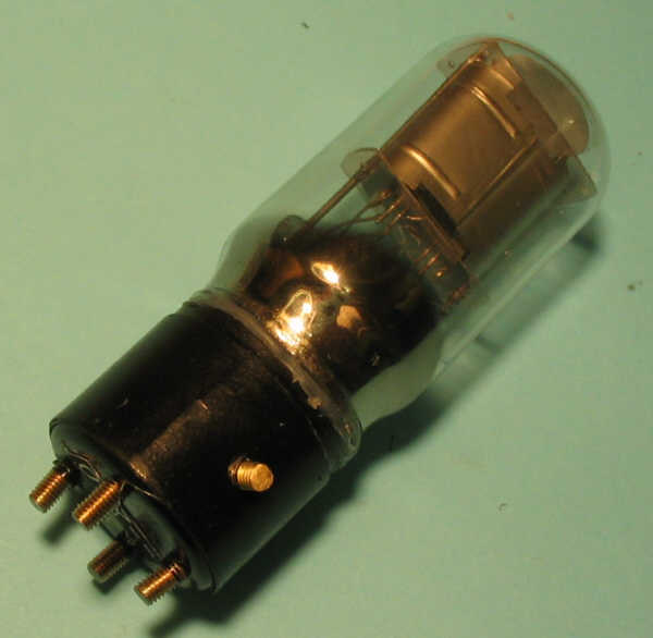
Their embase is "small 4-nub", about 25 mm diameter, with 4 identical nubs, positionned in accordance of the peaks of a about 12mm side square peaks.
The dimensions are not critical because the contacts are made on the termination of the nubs, on slats fairly broad.
The locking is done by one bayonet.
The embase height is about 20mm, while the original tube had a total height about 88 mm (including nubs).
The most critical point is to rebuild the bases.
Here's how to do.
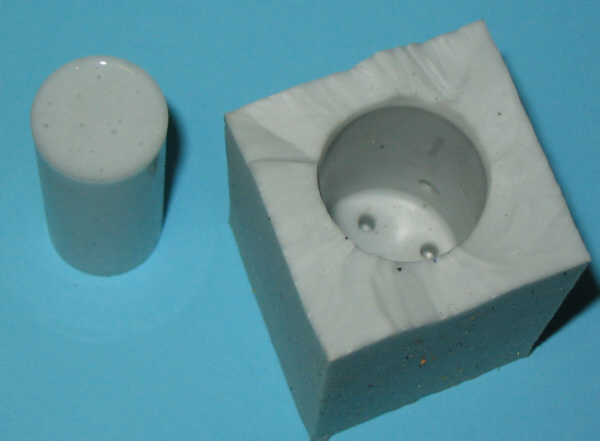
From a died capacitor 25 mm diameter, it is necessary to make a matrix.
On this matrix, I stuck 4 plots on its face and a fifth one for the bayonet, which is 4 mm long, while 4 others are 5 mm long.
The bayonet axis is just between 2 plots, and at a distance from the tip of the plots of 15 mm.
Just take a mould of this matrix with silicone rubber.
In a tube internal diameter of 18 mm, rubber is poured, it will be the inner cylinder mould.
This must be split along 4 generating lines, 90 degrees shifted , to a depth of 2 to 3 mm no more.
To pour the base, we must prepare:
-- A small piece of 3 mm threaded rod with a 10 mm length, that is inserted into the hole of the bayonet
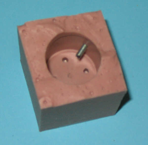
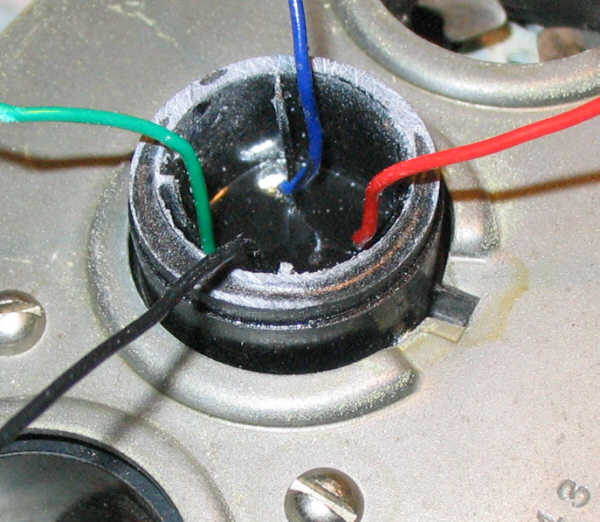
-- 4 flexible insulated wires (different colors) soldered on four 3mm diam. screws 3mm, 14 mm length.
These wires are inserted into the slots of the cylinder, the four screws are positioned in the end.
These are introduced into the 4 holes of the mould. Ensure good orientation of the four wires depending on their color (red = anode, green = grid, black = minus heating, blue = plus heating)
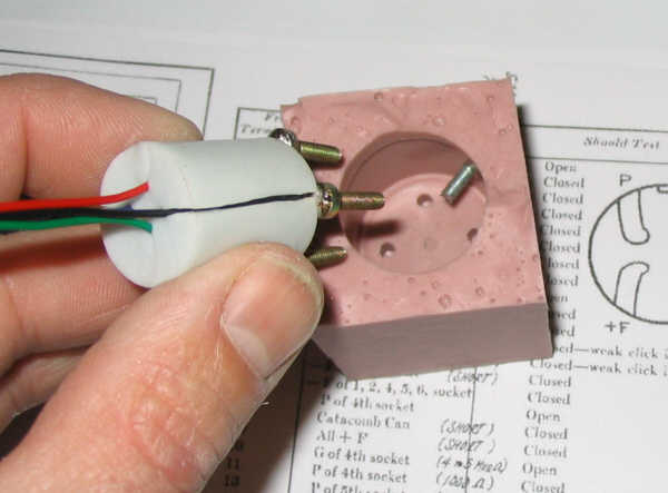
A notch in the end of the cylinder allows the passage of the screw of the bayonet.
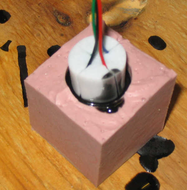
When black colored resin is poured, harding takes place within a few hours.
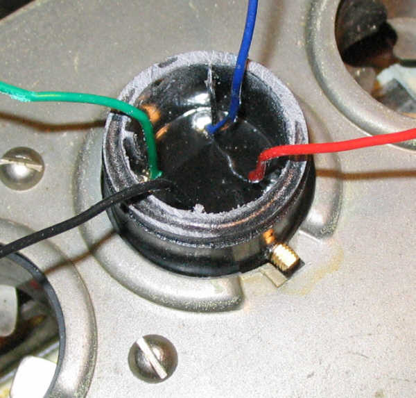
We must then verify that the base fit well in a catacomb of media, and is well maintained.
If it does not fit, you can try sanding lightly the resin.
If it does not locked, is that its diameter is too small, we must redo the mold.
In this case, we stick on the matrix few rounds of tape to increase the diameter and redo operations (except the inner cylinder)
If the lock is difficult, it is necessary to grind slightly bayonet and nubs ends.
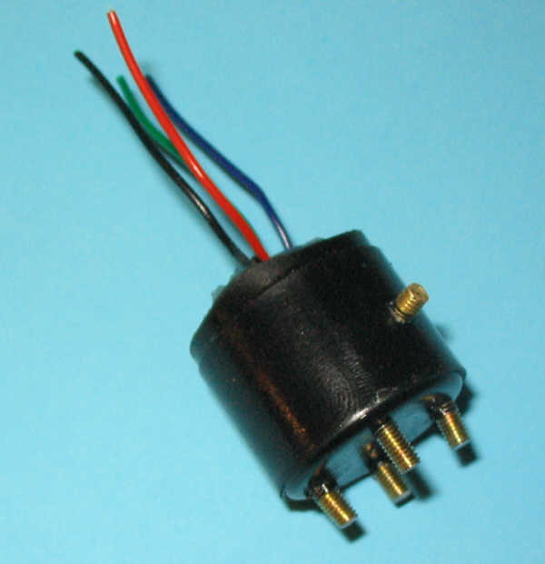
Normally, after a few tests, we get good bases that fit well and lock perfectly.
To achieve the "ersatz 99", I decided to use 3Q5s. These batteries pentodes really look nice.
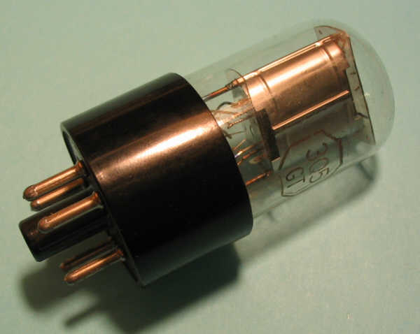
But first I have to make sure that I can use them with roughly the same characteristics as 99.
I made a quick installation for measuring the anode current by varying the voltage anode 90 to 100V and voltage grid -4.5 to -3.5 V.
I wired the 3Q5 in pseudo-triode mode (180kohm resistor between G2 and A)
Similarly, a 270 ohm resistor is wired in parallel with the filament to obtain a current about 60 mA for heating.
The obtained lamp is heated with 2.8 V (instead of 3V for 99) but it is not inconvenient, because there is a rheostat for tuning voltage battery.
Here are the results:
A) Vp = 90V Vg =- 4.5 V Ip = 2.4 mA
B) Vp = 100V Vg =- 4.5 V Ip = 3mA
C) Vp = 90V Vg =- 3.5 V Ip = 2.9 mA
from a) and b) we get: Rint = 16.7 kohm (internal res.)
and from a) and c) we get: s = 0.5 mA / V (transcond.)
What's really close to a 99! (Rint = 15.5 kohm, s = 0.425 mA / V for Ip = 2.5 mA)
I even made a measure in detection mode:
D) Vp = 45V Vg = 0V Ip = 1.8 mA
When these measurements are made, I can begin to make the first substitute (ersatz) "99-A".
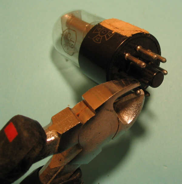
It is necessary to remove the base of the 3Q5; for this, it is best to cut the pins, then turn the base to break the glue.
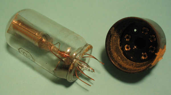
Here is a small outline to notice wires emerging from the base of the bulb
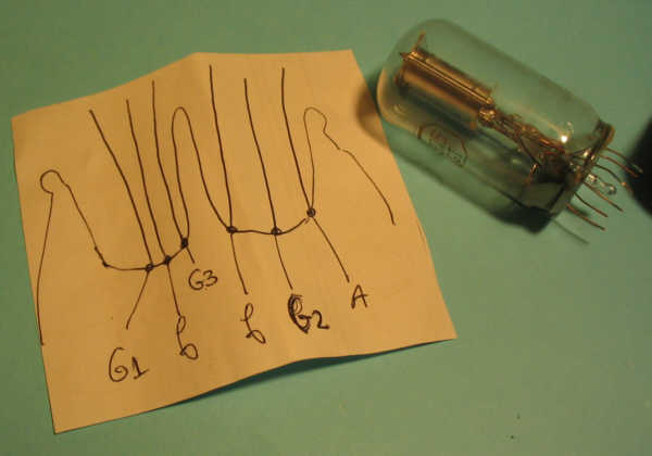
When the rests of glue are removed, we cut the wires near the base of the bulb, except wire of G3 which can be cut very small, because not used.
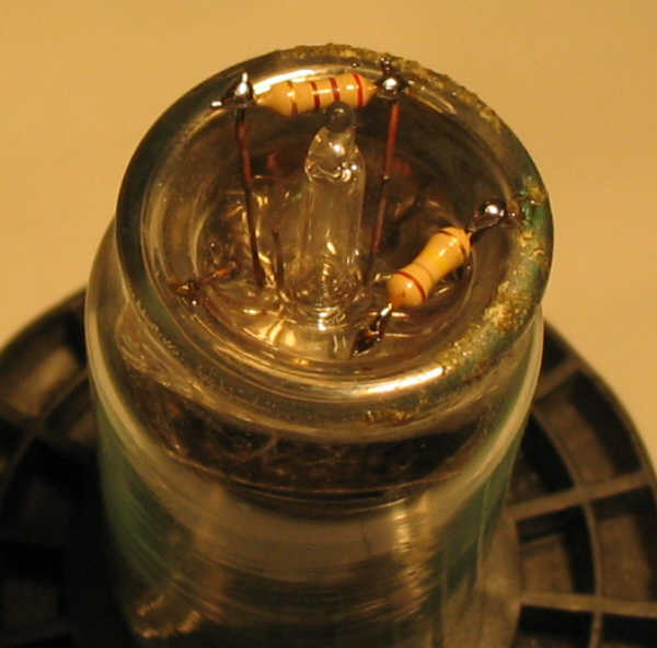
Then the 270 ohm resistor has to be solderer on the 2 wires of the filament, the 180kohm is soldered between anode and grid 2.
The 4 wires of the base are cut, keeping approximately 5 mm length above the upper side of the base and connected to the lamp.
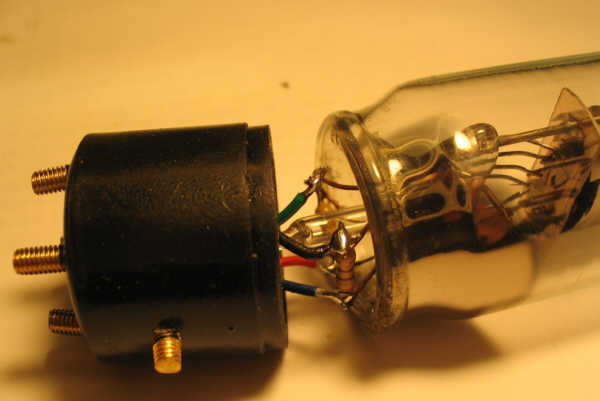
Then we glue using thermogun.
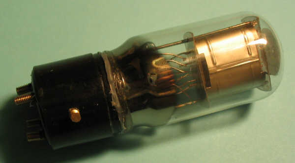
This is the first rebuild 99:
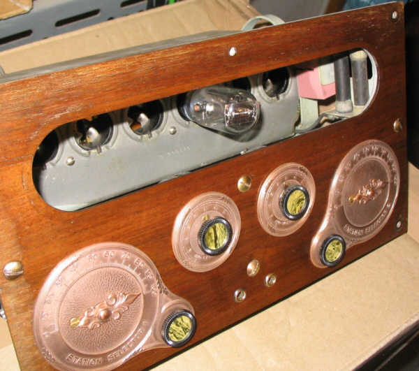
plugged on the Catacomb:
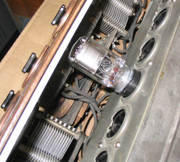
The lamp height is about 80mm; here is, seen from the front of the radio set: