Build a power supply
This supply must provide:
- heating voltage (originally, it's 4.5 V 360mA)
- bias voltage (originally, it's -4.5 V, in series with the 4.5 V heating battery)
- anodes voltage (45 and 90V)
It is not necessary that the heating voltage was 4.5 V because the original lamps and my own ersatz need only 3V;
Consequently, we can take a 3.5V for heating with a maxi intensity charge about 700mA (each 99-F ersatz consumes 110 mA)
The bias voltage is adjustable, because I want to see its impact on the radio set working. Initially, it was -9V;
During testing ersatz, I was able to set this voltage sometimes at -10, sometimes at -7V.
I expect to be able to set this voltage from -12V to -5V. This supply needs no intensity.
Anods voltage will be fixed at 90V, which may charge about 20 mA, and an adjustable voltage from 20 to 50V for the detector anod.
Indeed, I could see that the detector voltage had some influence on the operation. This supply should be able to charge about 2 mA.
Here is the power schematics.
 Power-supply
The settings will be available at the rear of the set, opening the battery compartment door.
The mains cord will pass through the bottom hole of the cabinet and can be completely retracted into the compartment when the radio is stored.
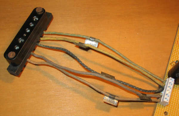
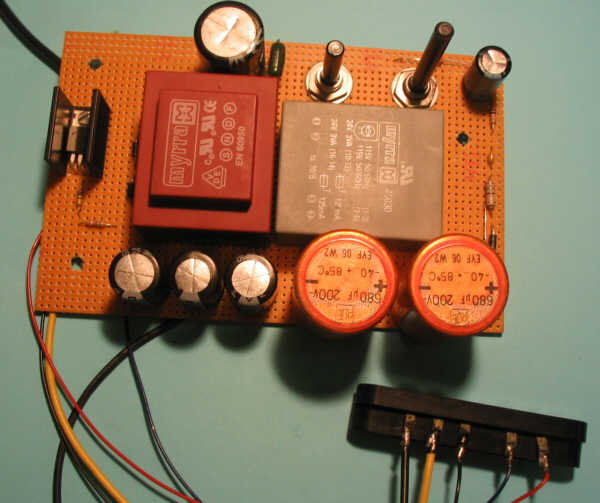
I wired the model on tests bakelit board. It's fast and this will allow modifications.
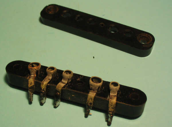
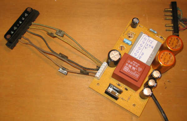
The connection of the 5 wires be done with the original connector.
It's very oxidized, it should be cleaned.
It can be disassembled because it is made of 2 parts joined by a screw, holding the 5 contacts:
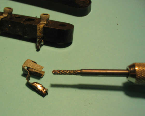
Each contact is deposited and cleaned with diamond cutter.
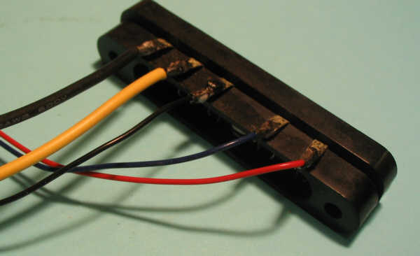
The 5 wires are now soldered to the reassembled connector.
Here is the power model
Results.
The radio set works perfectly with this power. There are no more reactions or snoring.
However, it sometimes happens Larsen, it seems caused by the detector lamp, which is really microphonic, by reaction with the HS which lies on the same board.
It remains to be seen, once the chassis installed in the cabinet, therefore suspended by the 2 rubber blocks, if Larsen always occurs, in which case it will be remedied.
The best settings for a correct receipt are:
- Baterry = 6
- Volume = 3
- - C = -9 V
- +45 B = +35 V
Under these circumstances, tensions are measured:
- +90 B = +98 V
- VA = -3.5 V (output heating supply)
- VA General = -2.37 V (heating lamps except detector)
- VA detector = -0.8 V (heating of the detector)
- I90B = 16 mA (total anodes intensity except detector)
- I45B = 1.1 mA (detector anode intensity)
- IA = 0.4 A (total heating)
Comments :
The optimal value of C is really -9V as original; it proves that the lamps (3D6) need the same bias as the V99's.
The anode voltage for optimal detection is +35 V instead of +45 V, but the difference on receipt between the minimum (20) and the maximum (+50) is not really significant.
The detector does not really need much heating (0.8 V)!
The intensity of 16mA anode is quite correct. We could use a fixed bias of -9V by using instead of the 1k potentiometer, 470 and 750 ohms resistors, only a single 560 ohm resistor(9 / 0016).
Similarly, the voltage for the detector could be set at +35 V by a resistors divider bridge, to remove the knob.
Here is the simplified power unit schematics:
simplified power unit
I used standard components, easy to find:
- Transformers: one that delivers 2 x 24V under 3VA each, the other one delivers 2 x 6V under 6VA each. Of course, you can use other transformers, such as a 48V / 6VA , 12V / 12VA and so on ...
- Capacitors are found in PC power supplies. The 680µF and 220µF are 200V insulated. The 100 µF, 25V insulated. The 3300 µF, 16V.
- Integrated regulator is a LM350 in TO220 case. A LM317T could agree as well. It needs an heat sink.
- Diodes are all 1N4007, but may agree 1N4004.
- 27k resistors are 1/2W (or two 56k 1/4W in parallel), the 2.2 k in series with the +90 B is a 2W; the 560 ohm is a 1/2W. All others are 1/4W.
Tensions and intensities indicated on the diagram were identified with the radio in operation, and Battery on "6", Volume on "3".
Now that power unit is finished, it's time to make connections to original connector.
I added a terminal on the power board, now I can disconnect it to replace or to check it without having to disassemble the connector from the cabinet.
Here is the whole power unit-connector:
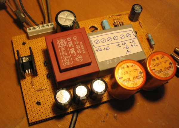
On power unit, I stuck a label identifying the terminal:
The original wires have been shortened to the same length and the metal tags have been cleaned: